LCD LED PLASMA TRAINING
My goal is explaining electronics repair in simple words….
Basic, Chip Level, Components Working
Hardware & Software
Welcome Friends
The reader/user is warned to consider and adopt all safety precautions to avoid all potential hazards. This BOOK/PAGE is for INFORMATIONAL PURPOSE only. The author cannot assume any responsibility for any loss, injury, errors, inaccuracies, omissions or inconvenience sustained by anyone resulting from this information. Most of the repairs tips and solution given should only be carried out by suitable qualified electronics engineers/technicians.
Android version update 12/03/2025 v4.7 release
Android version update 21/03/2025 v4.9 release
Android version update 29/04/2025 v5.0 release
New GLC Terminal
Windows Application

Windows Portable application v5.3.3
Prerequires for application development
Microsoft Visual Studio
Download link – https://visualstudio.microsoft.com/
Android Studio
Download link – https://developer.android.com/studio
Visual Studio Code
Download link – https://code.visualstudio.com/
SQLITE DB Browser
Download Link – https://sqlitebrowser.org/
XAMMP server and PHP
Download link – https://www.apachefriends.org/download.html
OFFLINE – ONLINE TRAINING CLASSES
- All topics regarding how to repair LCD/LED TVs.
- Circuit diagram tracing.
- PCB tracing.
- Voltage measurements.
- How to confirm voltage reading.
- Fault finding in cold test.
- Fault finding with DC voltage measurement.
- Calculation of voltage.
- Component working.
- Circuit working.
- Live Practical with original repair jobs
- Live software update, read write hands on
- eMMC re-balling practice
- Over 200+ circuit design tracing and fault findings.
- All types of circuit design explanation
- Working of PSU, MAIN BOARD, LED DRIVER and PANEL with fault findings.
- FREE GLC Droid (Android Application) and GLC TERMINAL (Windows Application)*
- Support in 2 TELEGRAM and 1 WhatsApp groups.
- For more details contact on +91 97232 17114 or mail me on anil.gorani@gmail.com
All images which I explain in my training with my handbook circuit diagrams.
OFFLINE TRAINING CLASSES
- Daily 11.00 to 17.00 classes
- Minimum 30 days classes
- Hard copy of training (Hand Book)
ONLINE TRAINING CLASSES
- On JIOMEET meeting every day 2 to 3 hours classes
- Live classes
- Minimum 30 days classes
- Soft copy of training (PDF)s
Applications developed by GLC
Serial Terminal tool for Android Board Diagnosis and Electronics Calculator
New updated versions for Android Mobile and Windows
Training Application
Interactive White board and Touch Display compatible user interface.

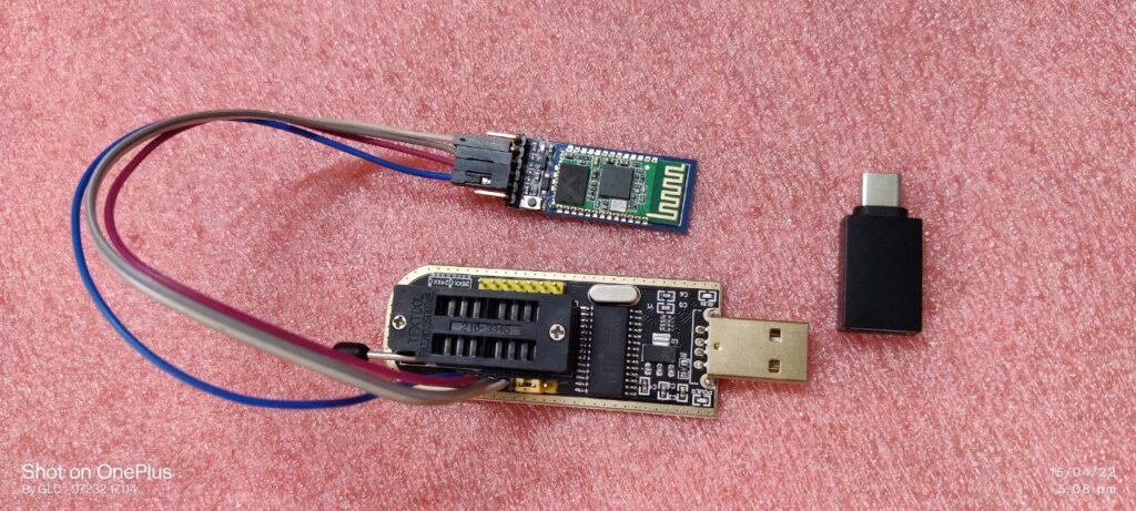
How to make ISP programming cables.
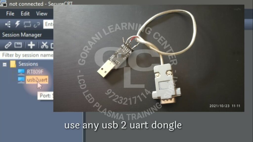
Connectivity cables require for ISP supported main boards…
supported devices with glc application
rx tx location on main board

how to repair back light
How to solve backlight problems in LCD – LED flat panel television sets.
Backlight driver circuit works on feedback called iSense, with ground point of backlight stripes at drive IC. iSense changed due to leakage / short / open circuit in backlight LED stripes which detected by drive IC and protected.
Refer images how iSense effected by leakage / short / open circuit.
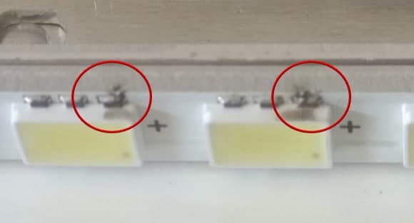
Leakage / short Circuit
Some backlight fault occurs due to metal support plate. Thin layer of insulation burn and voltage jumps / short with common ground and this changed iSense, detected by drive IC.
Replace LED stripe.
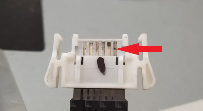
Open / Burn Circuit
Some backlight fault occurs due to FPC contact sparked/burn/open. Spark/burn spot generate open circuit and this changed iSense, detected by drive IC.
Replace with new FPC cable.
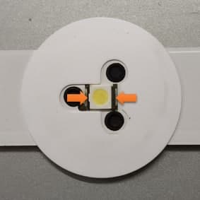
Open / Burn LED joints
Some backlight fault occurs due to solder material sparked/burn/open. Spark/burn generate open circuit and this changed iSense, detected by drive IC.
Replace LED or stripe as you do easily.
Open in socket joints
Some backlight fault occurs due to corrosion or spark generate open circuit and this changed iSense, detected by drive IC.
Clean track surface or Replace LED stripe.
Adaptive Dimming –
Adaptive dimming is a feature to improve contrast ratio designed in Backlight driver circuit divided in to two sections, 1.Local Dimming and 2.Adaptive Dimming
Local dimming starts first to show logo on screen in full lit backlight. All backlight stripe lit same time and same dimmer voltage.
After that picture information collected from TCON/LOGIC and controlled dimmer as per image condition. Backlight stripes lit individual as per picture frame information, brighter or darker.
Adaptive dimming section provide ground individual to all stripes.
How to Remove backlight protection
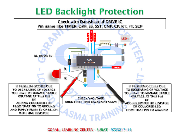
Normally all repair job workers wants to bypass all circuits in easy way.
Very first understand that you are not a manufactures. Design a good working module is not your job. So please know or learn a basic working principle of hard working engineers design and do only repair work no modification.
Here I explain only repair work tips and risk is yours, if you didn’t know basic of that PCB don’t try to repair it.
Backlight drive stop working when iSense is changed or abnormal or mismatched. Detected by backlight drive IC, called as invertor or LED driver. Detection pin mark as above image. Just like in invertor for fluorescent tube backlight TIMER or OVP, and in LED backlight driver SS, SST, CMP, CP, RT, FT, SCP
When fault occurs in backlight section voltage difference is measured on this pins which one you find in drive IC datasheet, you find one or two names in drive IC datasheet.
How to find eMMC Pinout with simple DMM.
CLK – CMD – D0
Here I describe how to find eMMC pin out like CLK, CMD & D0 using simple Digital Multi Meter. This technique Very first introduce and explained in my Training Seminar at SASAN SEMINAR 2018 conducted by Gorani Learning Center – Trainer Anil Gorani
Now this simple method/technique explained in all Training Seminars.
Only 4 steps and you can successfully find/identify on 9 out of 10 mother boards with this simple method.
step 1
Identify eMMC chip by it’s connection tracks, from eMMC to Main Processor IC on main board.
- You find 13 connection tracks.
- 2 tracks – Supply and Ground
- 3 tracks – CLK, CMD and VCCQ or RESET
- 8 tracks – DATA lines ( D0, D1, D2, D3, D4, D5, D6 & D7 )
step 2
- Check supply – it’s 3.3v or 1.8v at input supply line.
step 3
Now try to check voltage reading on 3 tracks randomly
- If you get HALF value of supply then that point mark for CLK
- If supply is 3.3v then CLK point reading shows 1.5v to 1.8v
- If supply is 1.8v then CLK point reading shows 0.7v to 0.9v
- If you get LESS value of supply then that point mark for CMDJust like if supply is 3.3v then DMM show 3.26v OR if supply is 1.8v then DMM show 1.76v.
If meter reading equal to supply 3.3v or 1.8v then that track should be VCCQ or RESET.
step 4
Now D0 is hidden in 8 DATA line tracks. mostly it’s located on forth (4) number of track. Joint your D0 ISP connection and start to read software.
if you get READ TIMEOUT error change it to left or right. And try.
- With this simple voltage reading method you can find any eMMC chip ISP point to software programing…
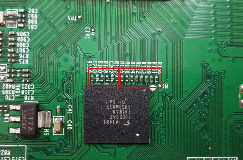
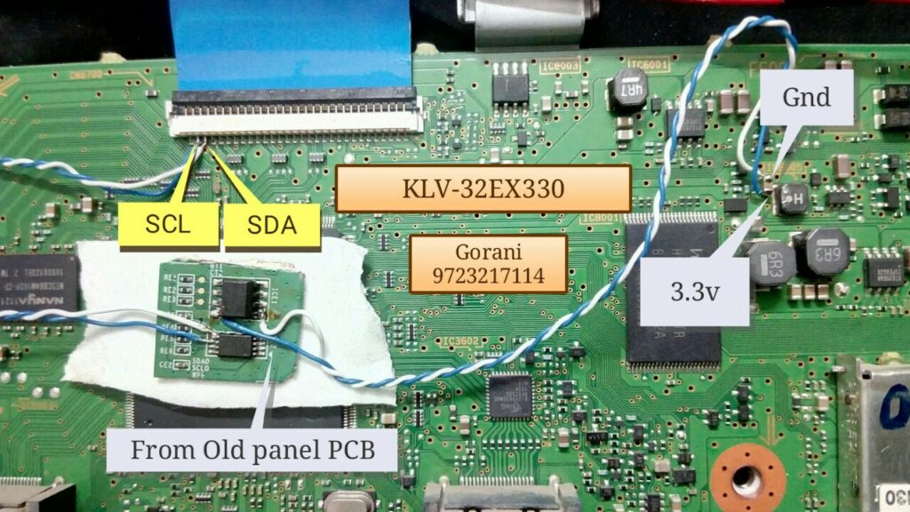
replace panel in sony lcd – led tv
In Sony sets mainboard processor connected with panel memory chip with bus line for panel ID. If this bus line is damage or panel id change then main board activate error blink and switch off in stand by mode.
Some time indicates GREEN and AMBER led blinks that means panel id is not matched, in this case you have to update mainboard software by USB stick. Get this update software from Sony Official Website.
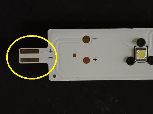
If bus line damage then indicates 5 time RED led blink. This situation also you face when you replace a new panel with same panel number or other locally available panel. In this case original panel id memory chip required to fix at mainboard as per above image. Fix that original chip using 4 connections,
1. 3.3v at pin no. 8
2. Ground wire
3. SDA connection from pin no. 5
4. SCL connection from pin no. 6
Or copy original chip data and paste it in new chip and fix it on mainboard as shown in above image.
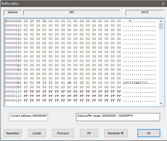
How to match your panel id which one replace in Sony set.
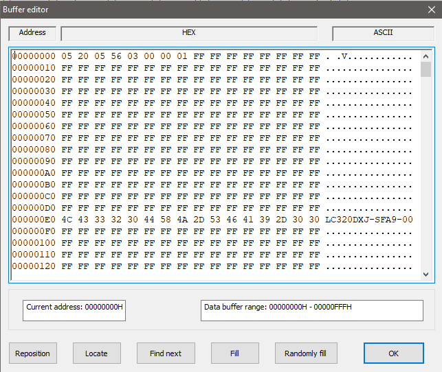
Using programmer, read memory chip data and check buffer. You find panel number in this buffer, change panel number as per your panel model number and rewrite in memory chip. And fix it on mainboard.
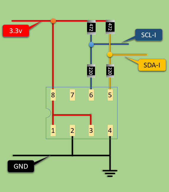
Make connection using ZERO pcb as per given diagram.
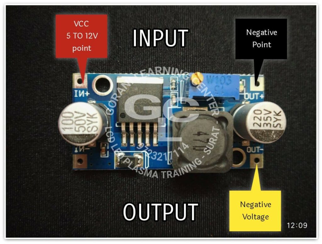
Convert positive buck converter into negative buck converter for VGL voltage
Very simple trick to convert positive buck converter into negative buck converter.
It is require to solve some panel problem by changing VGL voltage.
- Connect Input VCC wire to IN+ point
- Connect Ground wire to OUT+ point
- Get Negative Voltage from OUT- point